Not many can claim 25 years on the Internet! Join us in celebrating this milestone. Learn more about our history, and thank you for being a part of our community!
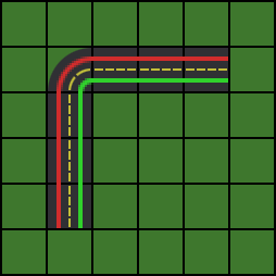
I am trying to create a traffic simulator but I am having trouble finding a good way to steer my vehicles around corners. The world is basically a 2D tile map where the corners/vertices of each tile can have different height, so basically a tessellated plane with heightmap. The vehicles driving the map are full 3D. Roads can just be laid out on flat tiles or straight slopes. See the picture below for reference (A orthogonal top view would look like this), the red and green lines represent the lanes and the path vehicles should follow.
Pathfinding is already solved but I am wondering what a good solution would be to move the vehicles and interact with them.
A simple approach would be to just rotate them at the corner, as for the reference above, by putting the origin in the bottom right of the corner tile and rotate the whole model clockwise. The problem is that I want to have different types of roads, and perhaps tracks that span multiple tiles which makes this difficult. Also, when the map raises in height, instead of a smooth curve there will be a corner, the tiles just consist of 2 triangles. I don't want the vehicles front part to clip trough the next tile which could be a maximum 45 degree slope.
Curves sound like a good solution. but I cannot get any good results with my attempts. In theory I would place the origin at the rear wheels and place that on the curve. Then I could calcluate it\s rotation by looking up the position on the curve where the front wheels would be.
The issue I have with curves is finding the right type of curve.
Catmull Rom seems the way to go since it spaces out it's points evenly, allowing me to move at the proper speed over the curve. But I just can't get the curve over the roads properly.
Bezier curves cannot be combined/merged properly afaik and it is not guaranteed that 0.1 to 0.2 has the same distance as 0.4 to 0.5 on the curve. Which brings me to same hacky solutions as the simple approach.
Another problem is the curves need to have both smooth transitions like the corners but when the road changes in height it needs to be a corner. Each tile consists just of 2 triangles.
And finally what is a good way to move and rotate a model over a curve. Do I need to hardcode where the wheels are and place it on the curve based on those values?
Eventually I want different types of roads and perhaps trains on rails that span multiple tiles so a solution that can handle that would be preferable. I also need changing lanes but this has proven too difficult to solve to even start thinking about that. A lot of games seem to have found a solution to my problem from Transport Tycoon to Cities Skylines I just cannot find the right information on the topic and it feels like I am reinventing the wheel here. I hope someone can point me in the right direction.
I’ve been working on paths for Mercuna’s off-road navigation middleware, so hopefully some of this is applicable for you. Depending on how much detail you want to go in to:
Curve following:
Having a vehicle `follow' a path usually involves choosing one point on the vehicle (e.g. the centre, or the midpoint of an axel) that is going to be fixed to the curve. The orientation then depends on your steering model. If one axel has no steering (e.g. the rear) then the simplest choice is to pick the midpoint of this to follow the curve, and then the orientation of the vehicle will be the direction of the curve. Once you've picked the curve point and vehicle orientation then the wheel placements follow, and the wheel orientations come from things like this (wikipedia).
Splines:
Bezier curves can be combined, you just need to set the final-tangent of the first curve to the start-tangent of the second. Presumably in your case you would set these at the interfaces of your tiles. At some point you are likely to need distance as a function of the curve parameter (e.g. to integrate velocities etc.). Again, depending how deep into this you want to go, you may only need Gaussian quadrature with a couple of points (wikipedia), though if you start making splines with very sharp corners then you'll need to add more. We've been using 2 parabolas sandwiched together at Mercuna, which makes things a little easier.
Thank you Peter, that are some nice pointers. In the meantime I made some process (I think).
First I tried calculating distances of waypoints (t) but this did only partially work. Some good results but sometimes it got very choppy and with large distances it would bug out. Code looked something like this, I heavily fiddled around with it so it might not work at all. The sprite itself actually moved all over the place but using nextPosition each frame gave me somewhat reliable results.
But like I said, this didn't yield exactly what I want. I fiddled hours with it and although I seemd very close to a working solution I started today with another method. This method maps positions on the curve and stores it. When looking up values on the curve it uses the mapped points to find a good approximation. I just got this done with great results. It also gives me the total length of the curve, so when the curve is 100 in length and my object needs to travel 40 this frame I can just call curve.findMappedPositionAt(.4f). I still need to find a way to calculate the proper angle/orientation but I guess I can just use the previous vector, next vector or perhaps I need vectors closer to each other on the curve at the current position. Here is the complete code with two additional methods to draw itself and the points at the divisions.
public class Curve
{
	private Vector2 a, b, c, d;
	private int length;
	private float[] arcLengths;
	private float totalLength;

	public Curve(Vector2 a, Vector2 b, Vector2 c, Vector2 d)
	{
		this.a = a;
		this.b = b;
		this.c = c;
		this.d = d;

		// Amount of mapping points.
		length = 100;
		arcLengths = new float[length + 1];
		arcLengths[0] = 0;

		float ox = this.findX(0), oy = this.findY(0);
		float currentLength = 0;

		// Build map for curve, higher length means better prediciton
		for (int i = 1; i <= length; i++){
			float x = findX(i * (1 / (float)length)), y = findY(i * (1 / (float)length));
			float dx = ox - x, dy = oy - y;
			currentLength += Math.sqrt(dx * dx + dy * dy);
			this.arcLengths[i] = currentLength;
			ox = x; oy = y;
		}
		// Set total length now we have it
		totalLength = currentLength;
	}

	/**
	 * Normal bezier curve calculation on 4 points
	 * @param t
	 * @return
	 */
	public float findX(float t){
		return ((1 - t) * (1 - t) * (1 - t)) * a.x
				+ 3 * ((1 - t) * (1 - t)) * t * b.x
				+ 3 * (1 - t) * (t * t) * c.x
				+ (t * t * t) * d.x;
	}

	/**
	 * Normal bezier curve calculation on 4 points
	 * @param t
	 * @return
	 */
	public float findY(float t){
		return ((1 - t) * (1 - t) * (1 - t)) * a.y
				+ 3 * ((1 - t) * (1 - t)) * t * b.y
				+ 3 * (1 - t) * (t * t) * c.y
				+ (t * t * t) * d.y;
	}

	/**
	 * Normal bezier curve calculation on 4 points
	 * @param t
	 * @return
	 */
	public Vector2 findPositionAt(float t){
		return new Vector2(findX(t), findY(t));
	}

	/**
	 * Bezier curve calculation using the mapped positions for linear interpolation of it's length
	 * @param u
	 * @return
	 */
	public Vector2 findMappedPositionAt(float u){
		return new Vector2(findUX(u), findUY(u));
	}

	/**
	 * This finds t for the regular bezier curve calculation using the stored intermediate points
	 * @param u linear position on the curve, 0.5 should return very close to half the curve.
	 * @return returns t to use on a regular bezier calculation
	 */
	public float map(float u){
		float targetLength = u * arcLengths[length];
		int low = 0, high = length, index = 0;

		while (low < high)
		{
			index = low + (((high - low) / 2) | 0);
			if (arcLengths[index] < targetLength)
			{
				low = index + 1;
			} else
			{
				high = index;
			}
		}
		if (arcLengths[index] > targetLength){
			index--;
		}

		float lengthBefore = this.arcLengths[index];
		if (lengthBefore == targetLength) {
			return index / length;
		} else {
			return (index + (targetLength - lengthBefore) / (arcLengths[index + 1] - lengthBefore)) / length;
		}
	}

	public float findUX(float u){
		return findX(map(u));
	}

	public float findUY(float u){
		return findY(map(u));
	}

	/**
	 * Draw curve using normal bezier to reduce calls, if you need it's segments to be equally long use the UX methods that make use of the mapped positions.
	 * @param steps
	 */
	public void drawCurve(int steps){
		float stepSize = 1f / (float)steps;
		for (int i = 0; i < steps; i++){

			DebugDrawer.drawLine(findX(i * stepSize), findY(i * stepSize), findX((i + 1) * stepSize), findY((i + 1) * stepSize), Color.RED);
		}
	}

	/**
	 * Equally divides number of points on the curve.
	 * Use (int i = 1; i < divisions; i++) to display start and end point of the curve
	 * @param divisions
	 */
	public void drawDivisionPoints(int divisions){
		float stepSize = 1f / (float)divisions;
		for (int i = 0; i <= divisions; i++){
			DebugDrawer.drawCircle(findUX(i * stepSize), findUY(i * stepSize), 10, Color.BLUE);
		}
	}

	public float getTotalLength()
	{
		return totalLength;
	}

}
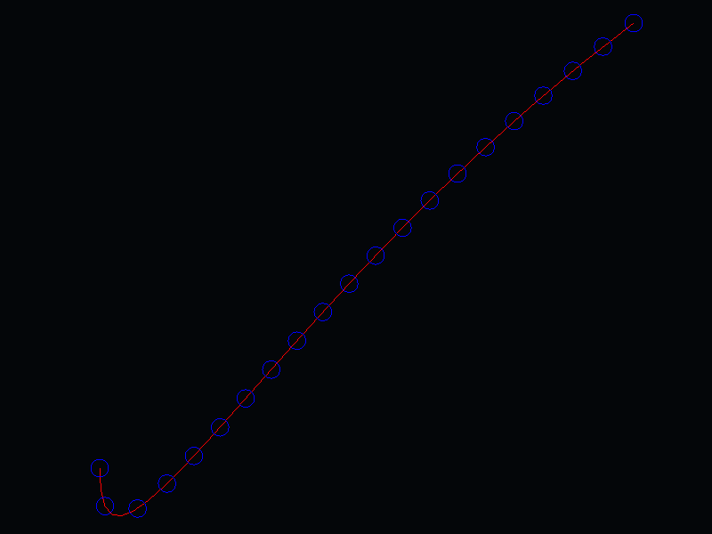
Here are the results on the following (very stretchy) curve:
curve = new Curve(new Vector2(-200, -200),
				new Vector2(-200, -400),
				new Vector2(0, 0),
				new Vector2(400, 300));
Linear division over the length of a bezier curve.
I don't think I need the steering wheel geometry, I think I will be fine with static wheels atm. But if I do want some extra detail this looks exactly like what I need to implement it.
I got some good results. It works perfectly on X/Z plane but could not get the rotation / quaternion to include Z. I'll try cleaning up some code and refactor a bit because it got messy in the end. Then I post some code, all I actually need is to rotate my model towards the purple line (front wheels). Currently doing this by using a fixed Vector.Y on the axis and calculating the angle between the back wheels and where the front wheel would belong on the path. The quaternion math was slightly off and it bugged out on some lines.